








GE Ultrasound Power Supply Repair: Troubleshooting Guide
The switching power supply is one of the most important modules inside a GE ultrasound system. It converts the incoming AC power into several stable DC voltages required by the system control board, imaging processor, display, front-end acquisition circuits, cooling fans, and other functional modules.
When the switching power supply develops a fault, the ultrasound system may fail to power on, restart repeatedly, display no indicator lights, shut down unexpectedly, generate abnormal images, or lose power to one or more internal modules.

Because a medical ultrasound power supply normally contains high-voltage rectification, power-factor correction, pulse-width modulation, high-frequency switching, multiple output rails, and protection circuits, technicians should not replace components without first identifying the affected circuit. A systematic, stage-by-stage troubleshooting process is usually more effective.
Switching power supplies contain hazardous voltages and high-capacity capacitors that may remain charged after the equipment has been disconnected from AC power. Inspection and repair should be performed only by qualified personnel using appropriate isolation, discharge, current-limiting, and electrical-safety procedures.
When repairing a GE ultrasound switching power supply, do not immediately connect the board to AC power. Begin with a careful visual inspection. Check the fuse, power resistors, electrolytic capacitors, rectifier bridge, switching transistors, high-power diodes, inductors, transformers, connectors, and printed circuit board for visible damage.
Common warning signs include burned areas, cracked components, swollen capacitors, discolored resistors, damaged insulation, loose connectors, carbonized circuit-board material, and broken solder joints.
Next, use a multimeter to test the main power components for short circuits, open circuits, or abnormal resistance. Important parts to inspect include:
- The AC input rectifier bridge;
- Primary switching transistors or power MOSFETs;
- High-frequency and high-current rectifier diodes;
- Inrush-current limiting resistors or thermistors;
- Input fuses and protection components;
- Output rectifier diodes and filter capacitors;
- Current-sensing resistors and gate resistors.
Measure the forward and reverse resistance between each output rail and ground. If one output rail shows an unusually low resistance, inspect its rectifier diode, filter capacitor, voltage-regulation components, and connected load circuit.
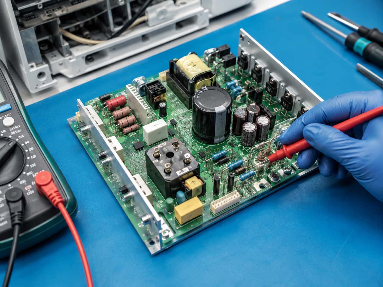
When a failed component is found, do not replace only the visibly damaged part. A shorted switching transistor, for example, may also damage the gate-drive circuit, current-sensing resistor, snubber network, PWM controller, or related protection components.
Replacement components should meet the original requirements for voltage rating, current capacity, power rating, switching speed, temperature characteristics, and package type.
After the preliminary inspection has been completed and damaged components have been replaced, the power supply may be tested under properly isolated and current-limited conditions.
If the power supply still does not start normally, inspect the pulse-width modulation circuit and the power-factor correction circuit.
The PWM circuit controls the switching transistor and regulates energy transfer through the high-frequency transformer. The PFC circuit improves the input-current waveform and, in many designs, raises the rectified DC bus voltage to a higher regulated level.
Before measuring these circuits, identify the controller part numbers and consult the corresponding component datasheets or model-specific service documentation. Technicians should understand:
- The normal supply-voltage range of the controller;
- The start-up and undervoltage-lockout conditions;
- The functions of the timing resistor and timing capacitor;
- The normal reference-voltage output;
- The feedback, enable, current-sense, and protection inputs;
- The expected waveform at the driver output.
Different GE ultrasound models may use different power-supply architectures. Test values should therefore be evaluated against the circuit design, controller datasheet, power-board markings, and applicable service information.
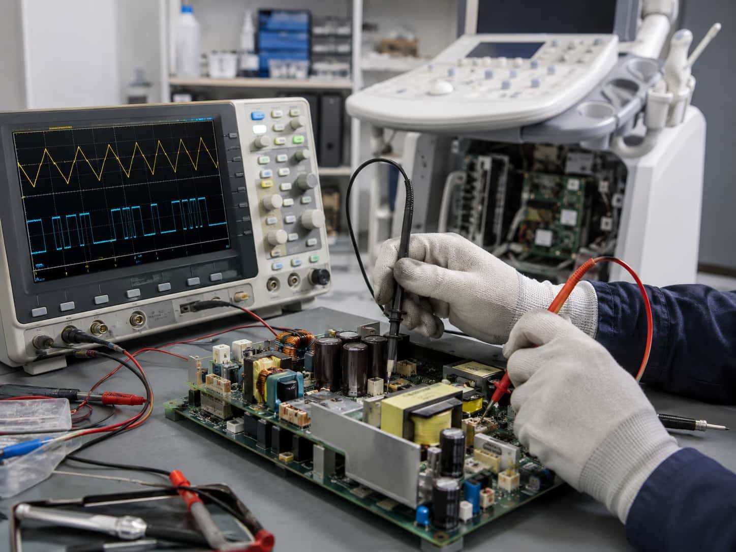
In a power supply equipped with a PFC stage, the DC voltage across the main filter capacitor can help determine whether the input rectifier and PFC circuits are operating.
With an input of approximately 220 VAC, the voltage after bridge rectification is commonly around 300 VDC. When an active PFC stage starts normally, the DC bus may increase to approximately 380–400 VDC, depending on the design.
| Measured Condition | Possible Interpretation |
| No high DC voltage | Check the AC input, fuse, EMI filter, inrush limiter, rectifier bridge, wiring, and main capacitor. |
| Approximately 300 VDC | The basic rectifier stage may be operating. Determine whether the specific design requires the PFC stage to raise the bus voltage further. |
| Approximately 380–400 VDC | The active PFC stage is likely operating, although waveform, stability, and load tests may still be required. |
If there is no voltage across the main filter capacitor, inspect the AC input circuit, fuse, EMI filter, surge-limiting device, rectifier bridge, capacitor, and related connections.
If the voltage remains at approximately 300 VDC in a circuit that should produce a higher PFC-regulated voltage, the rectifier stage may be functioning while the PFC boost stage is inactive. In this situation, inspect the PFC controller supply, start-up circuit, boost inductor, power MOSFET, fast-recovery diode, current-sensing resistor, and voltage-feedback network.
The main filter capacitor may retain a dangerous charge after the equipment is switched off. Confirm the voltage with an appropriate meter and discharge the capacitor through a suitable discharge method. Never discharge it by directly shorting its terminals with a wire or metal tool.
After confirming that the high-voltage DC bus is present, continue by checking the PWM controller.
First, measure the controller supply terminal, often marked VCC or VC. Confirm that the controller receives sufficient start-up voltage and that its supply remains stable after the power supply begins operating.
Next, check the reference-voltage output, start-control terminal, feedback input, current-sense input, and protection-related pins. An abnormal voltage on any of these pins may prevent the controller from producing a switching signal.
Under appropriately isolated test conditions, an oscilloscope may be used to observe the oscillator and driver waveforms. Depending on the controller, the CT terminal may show a clean sawtooth or triangular waveform. For example, the CT terminal of a TL494 circuit normally produces a sawtooth-type waveform, while other controllers may use a triangular timing waveform.
The output terminal should produce an orderly series of drive pulses. If the controller has a normal supply voltage but no oscillator waveform, inspect the timing resistor, timing capacitor, controller IC, and shutdown circuit.
If the oscillator operates but no output pulses are present, check the enable input, feedback loop, overcurrent protection, overvoltage protection, and undervoltage-lockout conditions.
If PWM pulses are present at the controller but the switching transistor does not operate, inspect the driver transistor, pulse transformer, gate resistor, isolation components, circuit traces, and the switching transistor itself.
Some ultrasound switching power supplies use eight-pin controllers from the UC38xx family, including the UC3842, UC3843, UC3844, and UC3845.
Common causes of failure in this type of circuit include:
- An open-circuit start-up resistor;
- An increased resistance value in the start-up network;
- A degraded PWM controller;
- A dried or leaking VCC filter capacitor;
- An abnormal auxiliary-winding supply;
- A damaged current-sensing resistor;
- A defective optocoupler or feedback circuit;
- Damage caused by a previously shorted switching transistor.
The start-up resistor normally supplies an initial charging current from the high-voltage DC bus to the controller’s VCC capacitor. If this resistor becomes open-circuit or increases significantly in value, the PWM controller may never reach its start-up threshold.
A degraded VCC capacitor can also produce repeated start-up attempts, intermittent clicking, abnormal noise, unstable operation, or failure to start.
A damaged start-up resistor should be replaced with a component that meets the original resistance, power, voltage, temperature, and safety requirements. Selecting a replacement only by physical size may result in repeated failure.
If the main DC bus voltage is missing, unstable, or not being boosted to the expected level, inspect the PFC circuit systematically.
Important PFC controller terminals may include:
- The VCC or VC supply terminal;
- The start or control terminal;
- The CT and RT oscillator terminals;
- The driver output terminal;
- The current-sensing input;
- The voltage-feedback input;
- The overvoltage and undervoltage protection inputs.
In addition to the controller IC, inspect the PFC switching transistor, boost diode, boost inductor, current-sensing resistor, DC-bus sampling resistors, and auxiliary supply.
A PFC fault is not always caused by a defective controller. An abnormal feedback signal, an incorrect sampling-resistor value, a missing auxiliary supply, a protection condition, or an excessive downstream load may prevent the circuit from starting.
For this reason, the diagnosis should be based on a combination of pin voltages, waveforms, component tests, and circuit operating conditions.
A GE ultrasound switching power supply may provide several voltage rails for different system modules. If the power supply starts but the ultrasound system still does not operate correctly, measure each output separately.
Typical output problems include:
- One output rail is completely missing;
- An output voltage is too high or too low;
- The voltage is normal without a load but falls under load;
- The output rises and falls periodically;
- The ripple voltage is excessive;
- The power supply shuts down after operating for a short time.
If only one output is abnormal, inspect the rectifier diode, filter capacitor, inductor, connector, solder joints, and load connected to that rail.
If several outputs are simultaneously too high or too low, inspect the main feedback loop, optocoupler, voltage reference, sampling resistors, and associated compensation components.
A deteriorated output capacitor may still produce an apparently normal average DC voltage when checked with a multimeter, while the actual ripple is excessive. An oscilloscope should therefore be used when output-ripple problems are suspected.
Long-term exposure to heat, dust, vibration, and repeated thermal cycling can create intermittent power-supply faults. Some failures appear only after the ultrasound system has been operating for a period of time.
Check the following areas carefully:
- Thermal pads or thermal compound between power devices and heat sinks;
- Cooling-fan operation and airflow;
- Dust accumulation around heat sinks and ventilation openings;
- Cracked solder joints on power components;
- Loose transformer and inductor pins;
- Oxidized, overheated, or loose connectors;
- Moisture damage, corrosion, or carbonized circuit-board material.
When a temperature-related failure is suspected, qualified technicians may perform controlled thermal testing while monitoring the relevant voltage rails and waveforms. All such testing should be conducted with appropriate electrical isolation and personal protection.
Restoring the power supply output is not the final step. After components have been replaced, the repaired board should undergo comprehensive functional and safety verification.
Confirm that all output voltages remain within their specified ranges. Check output ripple, load capacity, start-up behavior, temperature, current consumption, and protection functions where applicable.
After reinstalling the power supply, verify that the ultrasound system starts normally and that the imaging system, display, control panel, cooling system, data-acquisition modules, and connected probes operate correctly.
A suitable load or system-level burn-in test can help identify intermittent faults. During this test, observe:
- Whether the system restarts or shuts down unexpectedly;
- Whether any output voltage drifts over time;
- Whether power components become abnormally hot;
- Whether the cooling fan and airflow remain normal;
- Whether the power supply produces abnormal clicking or whistling sounds;
- Whether any burning smell or visible overheating occurs;
- Whether the complete ultrasound system remains stable during extended operation.
Although GE ultrasound switching power supplies may appear complicated, most designs can be divided into several basic sections: AC input protection, rectification and filtering, PFC correction, PWM control, high-frequency conversion, secondary rectification, multiple DC outputs, feedback regulation, and protection circuits.
A practical troubleshooting sequence is to proceed from the input stage to the rectifier, PFC circuit, PWM controller, switching stage, output circuits, feedback loop, and connected loads.
By understanding the function of each circuit section, identifying the operating requirements of the PWM and PFC controllers, and combining resistance, voltage, waveform, temperature, and load measurements, technicians can locate faults more accurately and reduce unnecessary component replacement.
Because ultrasound systems are medical devices and their power supplies contain hazardous electrical energy, repair work should be performed by trained personnel. The applicable GE ultrasound service documentation, component datasheets, local electrical-safety requirements, and medical-device servicing procedures should always take priority over general troubleshooting information.
GE HealthCare Service and Technical Support:
https://services.gehealthcare.com/gehcstorefront/contact
GE HealthCare Ultrasound Probe Management and Repair Services:
https://services.gehealthcare.com/gehcstorefront/ultrasound-probe-management
U.S. FDA — Remanufacturing and Servicing Medical Devices:
https://www.fda.gov/medical-devices/quality-and-compliance-medical-devices/remanufacturing-and-servicing-medical-devices
U.S. FDA — Guidance on Remanufacturing Medical Devices:
https://www.fda.gov/regulatory-information/search-fda-guidance-documents/remanufacturing-medical-devices
U.S. Occupational Safety and Health Administration — Electrical Safety:
https://www.osha.gov/electrical
OSHA — Electrical Hazard-Control Solutions:
https://www.osha.gov/electrical/solutions